 |
Services: Dual Fuel Conversion |
|
| Gas Fuel conversions of Diesel Engines. |
|
 Diesel engines may be converted to run on gas fuel in order to reduce running costs where natural or bio-gas fuels are available. In such cases, gas fuel is always more cost effective eg upto 90% saving. Diesel engines may be converted to run on gas fuel in order to reduce running costs where natural or bio-gas fuels are available. In such cases, gas fuel is always more cost effective eg upto 90% saving.
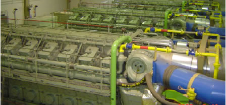 Most conversions of diesel engines are dual fuel because the cost of conversion is less than converting to a spark ignited configuration and the engine can still be run on diesel if no gas is available. In such cases, the engine behaves as a diesel with ignition of the diesel fuel by compression. The gas fuel is ignited in turn by the diesel . Even small quantities of diesel will be effective in igniting the gas because the energy of the diesel flame is much higher than that of a spark in a gas engine. Most conversions of diesel engines are dual fuel because the cost of conversion is less than converting to a spark ignited configuration and the engine can still be run on diesel if no gas is available. In such cases, the engine behaves as a diesel with ignition of the diesel fuel by compression. The gas fuel is ignited in turn by the diesel . Even small quantities of diesel will be effective in igniting the gas because the energy of the diesel flame is much higher than that of a spark in a gas engine.
Various dual fuel systems are available in the market and these are differentiated by cost and performance. The simplest versions involve introducing gas fuel at the engine air intake usually behind the air filter and sometimes on the pressure side of the turbocharger by means of some kind of valve. Although this method is very cheap, it is not suitable for larger engines due to the fact that in operation, the large engine intake manifold is filled with a combustible charge of gas and air. In the case of a large load rejection on a generator for instance, all of this mixture must be used up before the engine can unload.
|
| |
| Heinzmann Precision Control led Gas Injection System |
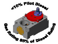
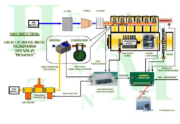 The system offered by Heinzmann overcomes all of the above issues and offers a very safe, efficient and well governed system. It results in a Pilot diesel level of <10% being used to ignite a gas air mixture and a dual fuel power rating of over 85%. Full power rating under normal diesel only running is unaffected by the conversion. The system offered by Heinzmann overcomes all of the above issues and offers a very safe, efficient and well governed system. It results in a Pilot diesel level of <10% being used to ignite a gas air mixture and a dual fuel power rating of over 85%. Full power rating under normal diesel only running is unaffected by the conversion.
Gas is admitted to each cylinder by individual "MEtering of GAs by SOLenoid" (MEGASOL) valves which discharge into a modified intake port of each cylinder.
|
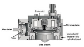
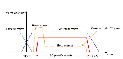
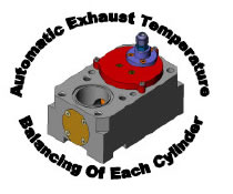
By means of camshaft and flywheel sensors the injection is accurately timed to begin only after the corresponding inlet valve has opened and exhaust valve has closed. The system therefore does not expose the engine intake system, turbocharger or hot exhaust to a combustible gas air mixture and therefore promotes the highest levels of safety. Also, because the gas fuel is injected close to the cylinders, the quality of governing of the engine is maintained at a similar level to that experienced when running with diesel fuel only. The amount of gas injected is controlled by the duration the of the MEGASOLs opening during each injection. Gas flow rate is substantially constant during the injection period which ensures the quantity of gas injected is proportional to the time the MEGASOLs are open. It also allows each cylinder to be individually controlled and allows the engine to be balanced correctly - usually by exhaust temperature monitoring.
|
 Gas fuel is taken from the customer's supply,
eg land fill, bio gas or natural gas supply. It needs to be supplied to the engine at a pressure greater than that of the charge air manifold in order to force the gas into the cylinder. It is therefore recommend that a
supply pressure of around 5-6 bar is used. Gas fuel is taken from the customer's supply,
eg land fill, bio gas or natural gas supply. It needs to be supplied to the engine at a pressure greater than that of the charge air manifold in order to force the gas into the cylinder. It is therefore recommend that a
supply pressure of around 5-6 bar is used.
The gas fuel flow to the engine is controlled by a shutoff valve, pressure reducing regulator and then delivered at around 4.5 bars pressure to the gas injectors which are fitted in the intake ducts ahead of the intake valves for each cylinder.
|
 A pressure sensor indicates available gas pressure and is used as a safety
feature to return to diesel running if the gas supply fails. A pressure sensor indicates available gas pressure and is used as a safety
feature to return to diesel running if the gas supply fails.
The gas injection quantity is electronically controlled according to the load of the engine. The governor ensures that sufficient diesel fuel is injected to maintain the ignition source for the gas fuel while keeping the diesel injection to a minimum. The system also prevents the engine being overloaded and observes boost pressure limitation when loading the engine.
|
| |
| Installation of the System |
|
The Heinzmann dual fuel system can be installed on diesel engines with 6 to 20 cylinders rated between SOOkW and 5MW.
Mechanical changes to the Engine
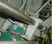 In most cases the existing diesel fuel actuator will be replaced with a modern high accuracy positioner. The remainder of the diesel system will be unaltered. Note that in order to gain the most benefit from a dual fuel conversion it is
important that the system uses as little diesel as possible. We know from experience that this can be as little as 7% diesel fuel however this is dependent on the condition of the existing fuel injection system and we would therefore recommend the injectors are serviced. In most cases the existing diesel fuel actuator will be replaced with a modern high accuracy positioner. The remainder of the diesel system will be unaltered. Note that in order to gain the most benefit from a dual fuel conversion it is
important that the system uses as little diesel as possible. We know from experience that this can be as little as 7% diesel fuel however this is dependent on the condition of the existing fuel injection system and we would therefore recommend the injectors are serviced.
To achieve minimum diesel consumption at part loads, it will be necessary to fit a waste gate or charge air bypass valve in order to control the fuel air ratio at part loads. This would be controlled by the Heinzmann unit.
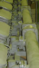 The system will feature a MEGASOL gas injection valve arranged to inject fuel gas into the intake port of each cylinder (one valve per cylinder). The installation of the gas injection valves requires modifications to the intake manifold sections of the engines. Existing designs are available for some engines. The gas injection valves will discharge into a pipe tail which will project through the intake manifold and into the intake ports of the respective cylinders. On the supply side the MEGASOL valves are all fed from a new gas supply manifold run above the original intake manifold (two gas supply manifolds in the case of the V engines). The manifold will be sized according to the fuel gas flow and pressure and will be approximately 75-150mm and will feature a gas pressure sensor which will allow the controller to compensate for changes in gas supply pressure and also trip to diesel operation if the gas supply fails. The system will feature a MEGASOL gas injection valve arranged to inject fuel gas into the intake port of each cylinder (one valve per cylinder). The installation of the gas injection valves requires modifications to the intake manifold sections of the engines. Existing designs are available for some engines. The gas injection valves will discharge into a pipe tail which will project through the intake manifold and into the intake ports of the respective cylinders. On the supply side the MEGASOL valves are all fed from a new gas supply manifold run above the original intake manifold (two gas supply manifolds in the case of the V engines). The manifold will be sized according to the fuel gas flow and pressure and will be approximately 75-150mm and will feature a gas pressure sensor which will allow the controller to compensate for changes in gas supply pressure and also trip to diesel operation if the gas supply fails.
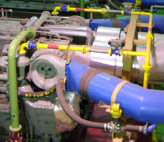 Connection to the gas main will be made through a double block shutoff system and an additional lockable
hand valve at the connection point to the gas main. These are to isolate the gas supply when the engine is not running on gas or in an emergency shutdown. The valves are air actuated and are controlled by small pilot solenoid valves closing to the failsafe position if the air supply is lost. The block valves have soft seals so that the shutoff is guaranteed and the valves close failsafe on loss of control signal or air supply. Connection to the gas main will be made through a double block shutoff system and an additional lockable
hand valve at the connection point to the gas main. These are to isolate the gas supply when the engine is not running on gas or in an emergency shutdown. The valves are air actuated and are controlled by small pilot solenoid valves closing to the failsafe position if the air supply is lost. The block valves have soft seals so that the shutoff is guaranteed and the valves close failsafe on loss of control signal or air supply.
In order for the controller to accurately time the gas injection, the system needs two reference speed pickup
signals, one from the cam shaft to give a phase position and one from the flywheel to give a TDC signal. This will
be achieved by the addition of two magnetic pickups and also a hall effect pickup to sense a phasing peg or notch on the cam gear. Actual location will depend on engine type.
It desirable that the engine is equipped with exhaust gas thermocouples which will be used to ensure that
each cylinder is generating a similar power. It should be noted that the cylinder pressure indicator cocks
should be removed when running on gas as a safety precaution to eliminate pockets when gas air mixture can
accumulate.
|
| |
| System Components |
 |
|
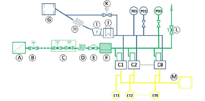
A complete gas installation is shown schematically below
Component Descriptions
A= Gas Filter
B= Pressure regulation valve. (Mechanical or controlled from Boost pressure depending on gas supply)
C=Safety Double shut 011 valve controlled from Heinzmann system
D=Flexible connection (If necessary)
E= Lockable isolation valve for use during maintenance
F= Flame arrestor (If required by safety regulations)
G= Air Intake filter
H= Flexible bellows
1= Compressor stage of Turbocharger
J= Intercooler
K= Boost Bypass Valve to maintain Air Fuel Ratio at all loads
L= Gas Manifold Vent (maintenance use)
M= Exhaust Turbocharger
TOI= Charge Air Temperature Sensor
POt= Charge Air Pressure Sensor
P03= Gas pressure Sensor
C1 etc= lndividual cylinders with Megasol Valves
ET1 otc-Exhaust branch temperature sensors.
All of the above equipment is available from Heinzmann UK
|
 |
|
| Electronic Changes |
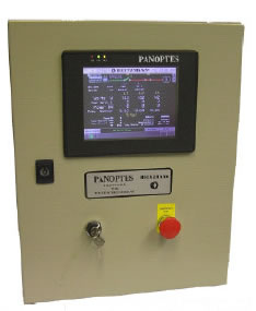 The control system upgrade includes a new control cabinet with essential operator controls which will be installed close-by each engine. The cabinet will contain the new governing system and operator interface allowing the selection of fuel type and provides a full display of all dual fuel parameters and alarms for all the dual fuel aspects of the system. Interfaces to the existing speed/ load control signals will remain. It also has all the necessary safety function and over speed protection. Note that for a dual fuel system on a V engine it is advisable to monitor turbocharger speed to check for imbalance between banks which may be the result of unburnt gas being burnt in the exhaust manifold causing the turbo charger to spin
faster than anticipated The control system upgrade includes a new control cabinet with essential operator controls which will be installed close-by each engine. The cabinet will contain the new governing system and operator interface allowing the selection of fuel type and provides a full display of all dual fuel parameters and alarms for all the dual fuel aspects of the system. Interfaces to the existing speed/ load control signals will remain. It also has all the necessary safety function and over speed protection. Note that for a dual fuel system on a V engine it is advisable to monitor turbocharger speed to check for imbalance between banks which may be the result of unburnt gas being burnt in the exhaust manifold causing the turbo charger to spin
faster than anticipated
On a normal installation, equipment such as motor controls (pre/ post lubrication, fuel treatment, air compressor etc.), synchronisation and load adjustment would be unaffected and remain as per the existing installation although HU K can offer a complete control system upgrade if required.
Additional options for control equipment include Oil Mist Detection, knock sensor and complete replacement control panels including power management.
|
| Dual Fuel Running |
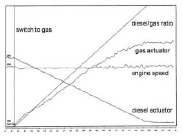 In operation the engines are started and synchronised on diesel fuel as normal. Once the load is above 25% and the engine water system is above 60C then the controller can be commanded to run on diesel fuel or dual fuel. In the dual fuel case, the load is fully taken by gas. Changes between diesel only and dual fuel on load is done by ramping a fuel splitter function in the controller. In case of breaker opening on load the control reverts to diesel only.
|
| Basic Requirements:- |
- Gas Supply available at 5-6 bar. (HUK can offer an engine driven compressor system if this pressure is
not available)
- 24Vdc power supply with 30 Amp capacity for each engine.
- Instrument air supply 6-8 bar at each engine. Very low consumption.
- Gas connection is by others and will require a 7 bar supply pressure to our connection point at each
engine (two such lines for 16 cylinder engine).
- The standard system assumes that the area is not designated hazardous. (ATEX requirements not
applicable).
|
| |
| What Next? |
|
Heinzmann can arrange for a dual fuel conversion on your engine including all the mechanical components,
control system modification, testing and commissioning and training of operators.
|